flyARIA Technical Tour
How ARIA Worked
Droop snoot, S-band, PMEE consoles, and the crew who flew the mission
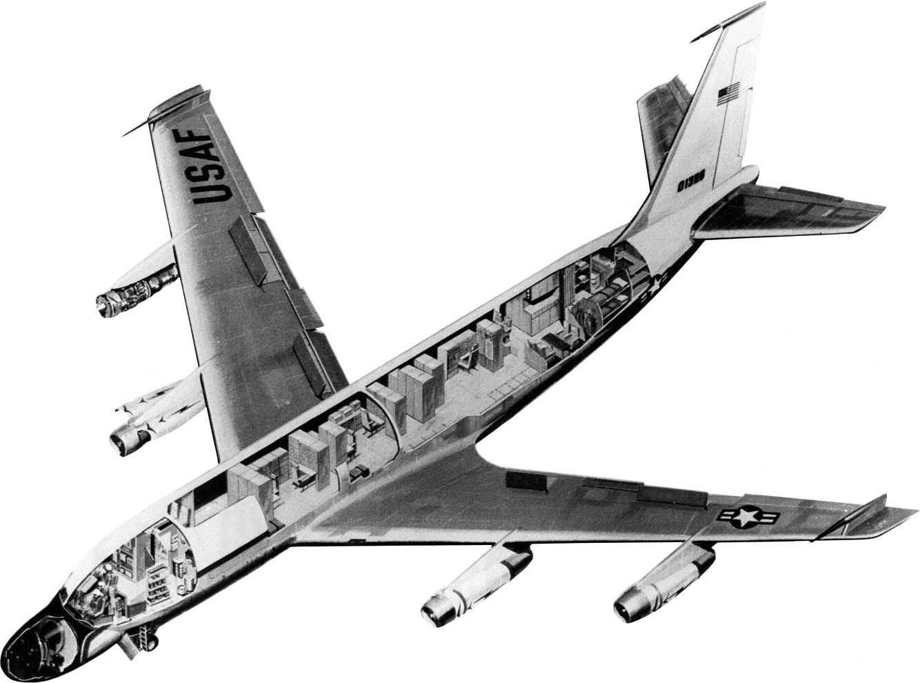

ARIA was a flying radio station. When Apollo spacecraft — and later missiles and other space vehicles — flew over oceans beyond the reach of land stations and instrumentation ships, an EC-135 with a bulbous nose could be on station to hear them, talk to them, and bring the data home.
This tour explains how that worked: the “droop snoot” nose and its steerable dish, the S-band and related radios, the Prime Mission Electronic Equipment (PMEE) consoles in the cabin, and the crew roles that made a support pass succeed. It is written for families and space enthusiasts as well as for people who flew or worked the system. Detailed console pages already live under Equipment; the links below take you there without repeating every panel label.
Deep console detail already lives under ARIA Equipment. This tour explains the system those consoles served. For the program story, see The Beginning, NASA Apollo, the fleet — including TRIA, EC-18, and ALOTS — and deployment sites.
Why an airborne station
Apollo’s lunar missions needed continuous or near-continuous contact during critical phases — especially the second burn of the Saturn V’s third stage that sent the spacecraft toward the Moon (translunar injection), and later the fiery return through the atmosphere. Large parts of those ground tracks crossed open ocean, where fixed antennas and even the Apollo ships could not always be in the right place at the right time.
NASA and the Department of Defense agreed to instrument eight long-range jet aircraft as mobile stations. Converted from C-135 transports at Douglas Aircraft in Tulsa and redesignated EC-135N, the Apollo Range Instrumentation Aircraft came online in January 1968 and were operated for NASA by the Air Force Eastern Test Range from Patrick Air Force Base, Florida. After Apollo, the same idea — a quick-reaction airborne range station — continued under the name Advanced Range Instrumentation Aircraft from Wright-Patterson and later Edwards.
Six aircraft typically needed to be on station for a major Apollo support, with two held as spares. Staging bases worldwide — Ascension, Darwin, Diego Garcia, Hickam, and dozens of others — put the airplanes under the flight path before the critical event.
The Beginning Apollo program Deployment sites Patrick AFB
The droop snoot
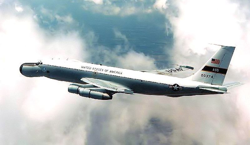
The feature everyone noticed was the nose. A roughly ten-foot radome — nicknamed the “droop snoot” — replaced the ordinary C-135 nose. Inside it sat what contemporary Air Force and NASA materials called the largest airborne steerable antenna of its kind: a parabolic dish about seven feet across (some period booklets say seven and a half).
That dish was the front end of the Voice and Telemetry system’s Antenna Group. It acquired the spacecraft and held track, either under manual pointing from the antenna operator or in automatic track when the received signal was strong enough. Signals from the dish went through preamplifiers before they reached the receivers in the Radio Frequency group.
Outside the nose, other antennas completed the picture: HF probe antennas on the wing tips, an HF trailing-wire antenna that could be reeled out under the belly in flight, and VHF/UHF antennas for spacecraft voice and telemetry paths. The bulbous radome is what made an ARIA unmistakable on the ramp or in photographs — including ARIA 60-0374, now displayed at the National Museum of the U.S. Air Force.
Antenna Control Console Aircraft 60-0374 The Last ARIA
Signals and S-band
ARIA’s job was to receive and record telemetry, and — on crewed flights — to relay voice between the spacecraft and Mission Control. Period range materials describe reception in the P-band (about 225–260 MHz) and S-band regions used for spacecraft and missile telemetry. On flyARIA the S-band mission band is summarized as 2200–2400 MHz, the neighborhood of the unified S-band and related space/telemetry allocations ARIA was built to serve.
For Apollo voice, the aircraft could work the spacecraft on VHF and on the unified S-band system, and could operate so that Houston’s words reached the crew through the airplane. Downlink voice received on the aircraft could be selected and sent onward. High-frequency (HF) radios tied the airplane to the Aircraft Operations Control Center for flight following and mission updates on deployment, and during Apollo also carried the remoting path that connected spacecraft communications on the airplane with the HF net to the ground.
Telemetry and related signals were recorded on wideband magnetic tape with mission timing so that events could be reconstructed later. In flight, recorded data could also be transferred (“data dumped”) to a NASA ground station that then forwarded it by landline to Houston or other users. Later missions added options such as Space Ground Link Subsystem (SGLS) receivers for Air Force missile formats, and — on some airframes — optical or sonobuoy scoring gear for range work beyond Apollo.
RF Console HF Console Timing and Record
PMEE consoles
Inside the cabin, the Prime Mission Electronic Equipment — PMEE — was the instrumentation suite that turned a transport into a range station. Banks of consoles faced operators who ran antenna control, radio frequency, mission coordination, HF communications, timing and recording, and specialized data paths. The Mission Coordinator supervised the PMEE crew from a master console that showed subsystem status, antenna angles, and timing.
An Operational Maintenance Training Unit (OMTU) on the ground duplicated the PMEE layout, with a matching steerable dish in its own radome, so crews could rehearse acquisitions and failures before they flew. The Equipment section of this site keeps the individual console pages from the archive; use them for panel-level detail. This tour stays at the system level.
Antenna Control Console
Points and tracks the parabolic dish — manual or auto-track.
Radio Frequency Console
Receives and processes VHF, UHF, and S-band spacecraft signals.
Mission Coordinator Console
Master status board for the PMEE crew during a support pass.
High Frequency Radio Console
Voice and teletype to the ground; Apollo remoting path to Houston.
Timing and Record
Wideband tape recorders and mission timing for the tapes.
Data Separation Console
Special instrumentation, SGLS, and data buffering.
OMTU
Ground trainer with a matching dish for PMEE crew practice.
SMILE / OPTICS
Later range work: sonobuoy impact scoring and optical tracking.
Crew roles
An ARIA flight carried a standard aircrew to fly the airplane and a PMEE instrumentation crew to run the mission electronics. Titles and manning shifted over three decades, but the published picture is consistent: a Mission Coordinator directed the PMEE team; operators sat the antenna, RF, HF, recording, and other consoles; and maintenance and training kept the suite ready between deployments.
The antenna operator worked the Antenna Control Console — slewing and tracking the seven-foot dish in the droop snoot, switching between manual and auto-track, and watching signal quality so the RF operators had a clean downlink. Site owner Randy L. Losey was the antenna operator on ARIA 60-0374, the last of the original eight, now at the National Museum of the U.S. Air Force in Dayton.
None of this page invents classified procedures or unpublished personal stories. Crew who flew the line, and families who hold logbooks and photographs, are invited to add to the archive by email — there are no forms on flyARIA.
About Randy L. Losey ARIA Roster 60-0374 dossier
On station
A support began long before the spacecraft rose. Aircraft deployed to staging bases along the planned ground track, checked out PMEE, and waited for the launch or burn window. On station, the Mission Coordinator ran the countdown against the published timeline while the antenna operator searched along the predicted look angles.
When the spacecraft rose into view, the dish locked — manually at first if needed, then often in auto-track. RF operators confirmed telemetry and voice quality; recorders ran with timing; HF kept the airplane tied to the control center and, on Apollo, to the remoting net. After the pass, tapes and voice logs were the mission product, sometimes dumped in flight to a ground site, always protected for the using agency.
The same pattern scaled from Apollo reentry corridors to later DoD and NASA tests: put a calibrated airborne station where the geometry demanded it, acquire, record, relay, and recover. That is how ARIA worked.
Deployment Sites Air Force Bases ARIA History ARIA Media
Add to this tour
Photographs of consoles, clear cockpit or cabin shots, training notes, and corrections from ARIA crews and families help keep this accurate. Write to [email protected] — there are no forms on this site.
Technical descriptions on this page follow public NASA and U.S. Air Force range materials (including period ARIA booklets and STDN/network procedures), the Cape Canaveral Space Force Museum’s ARIA summary drawn from those booklets, and the existing flyARIA Equipment and History archive pages edited by Randy L. Losey. Dish size, radome size, frequency bands, and console roles match those published sources. Classified or restricted details are omitted on purpose. Photographs: NASA cutaway (67-H-1237) and U.S. Air Force in-flight photo of 60-0374. Works of the U.S. Government are generally in the public domain in the United States; credit does not imply endorsement.